

The determination of stresses adjacent to copper through-silicon vias (TSVs) is a very important task in cutting-edge microelectronics. These copper contacts, with diameters of 5–10 μm, are placed inside silicon chips and are used to interconnect different chip levels in stacked 3D microelectronics. Due to the higher coefficient of thermal expansion, copper displays a stronger volume shrinkage than silicon, and during cooling down from the annealing temperature of 350 °C to room temperature, high mechanical stresses are induced in the silicon around the TSVs. This can cause reliability problems and change the electrical parameters of the transistors in the vicinity of the TSVs.
These effects can be controlled through measurement of the micro-stress state in 3D electronic structures. The FIB-DAC method was implemented for this. The name “FIB-DAC“ stands for “Digital Auto Correlation“ of scanning electron microscope images before and after material removal with the “Focused Ion Beam“ technique. In detail, the following steps are performed:
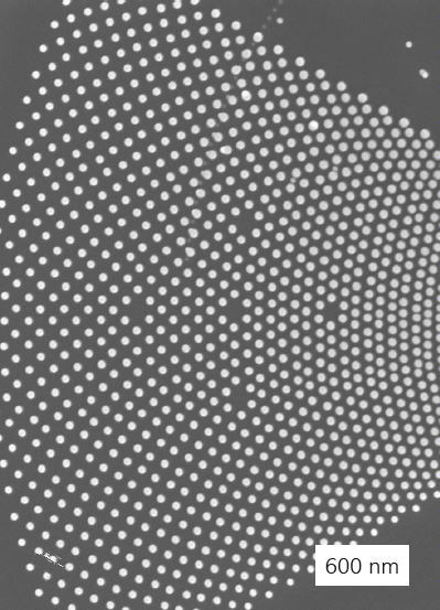
Step 1: A stable high-contrast pattern with no translational symmetry is created on top of the region of interest (ROI) by deposition of platinum micro dots.
Step 2: An initial high-quality micrograph of the ROI (Figure 1) is taken with a scanning electron microscope.
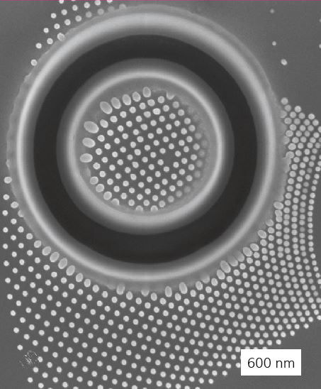
Step 3: All material around the ROI is removed through milling of a circular slit with a focused ion beam; relaxation of the inplane stresses results in small amounts of expansion/contraction (depending on the previous stress state) in the ROI.
Step 4: A second high-quality micrograph of the ROI is taken (Figure 2).
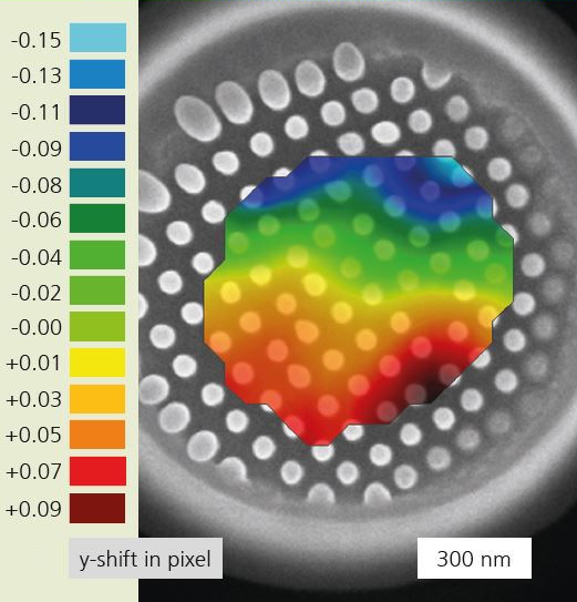
Step 5: The resulting strain field is calculated with subpixel accuracy using image correlation software (Figure 3).
Step 6: The stresses are calculated from the strains using either numerical or analytical solutions of the local geometry.
The authors gratefully acknowledge the European Union for the funding in the context of the project “iSTRESS”, grant agreement no: 604646.
