 Fraunhofer Institute for Ceramic Technologies and Systems IKTS
Testing machine for CT units
Current research
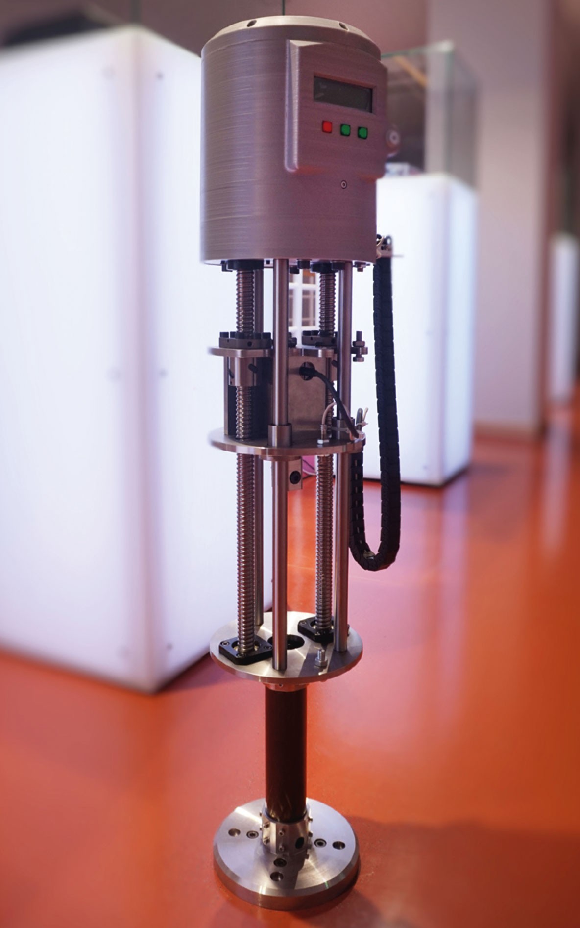
General view of the testing machine for loading in CT units.
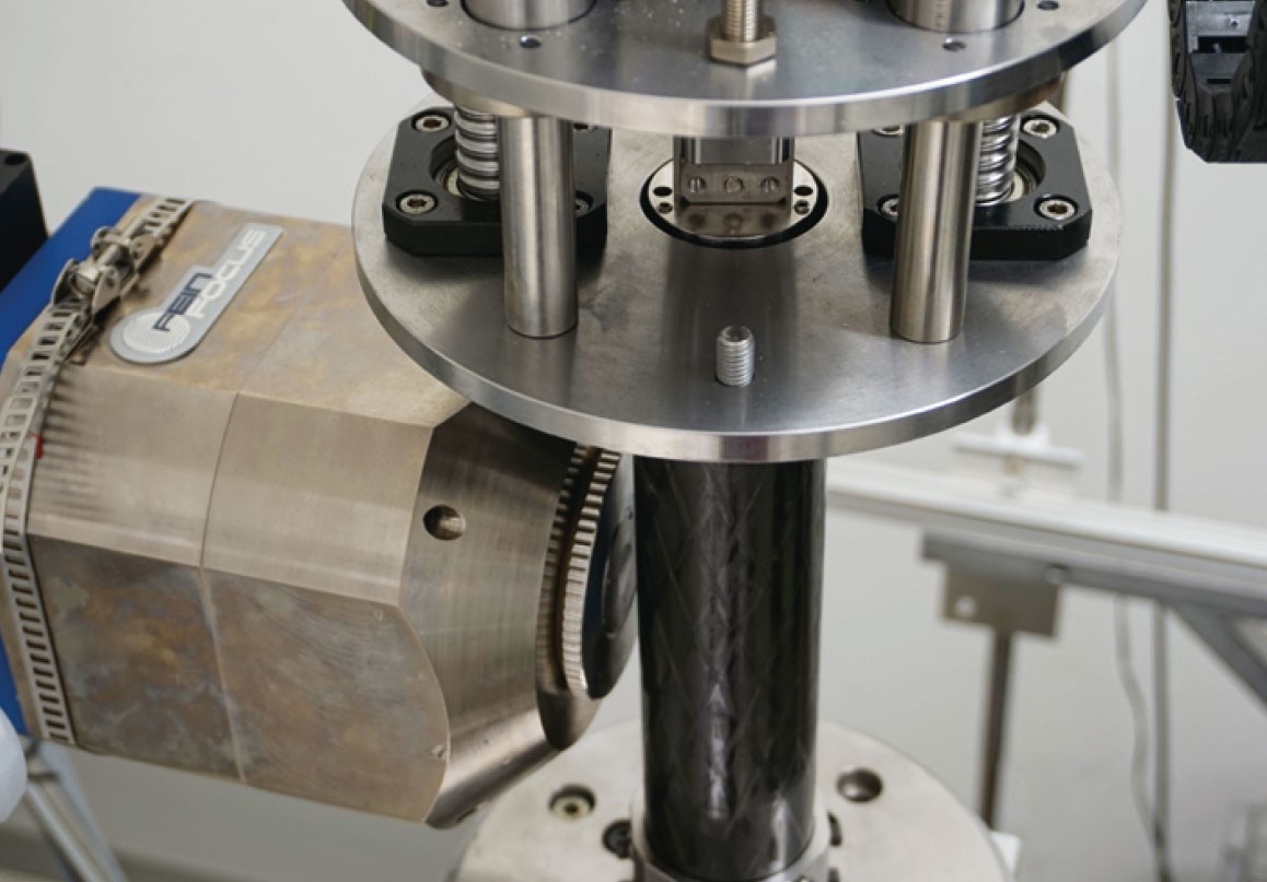
The specimen assembly is pushed into the CFRP tube from above.
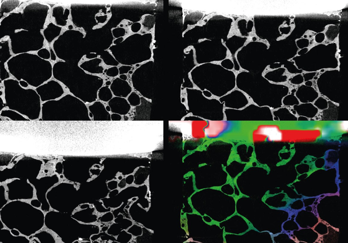
Compression test of an aluminum foam: Different stages, color-coded displacement vectors.
Composite materials get their properties from the combination of their components. Different failure variants occur in loading scenarios. Temporal stages of failure (e.g. fiber or matrix fractures in fiber composites) can often be visualized using computer tomography (CT).
For highly structured materials, such as foams, it is the morphological changes under load that are of interest. This is especially true for the design of biocompatible materials that can serve as bone substitutes. The porous structure of the substitute materials as well as the bonding to the bone are of particular interest for investigation.
Principle behind the machine integrated into the CT
A test setup that applies different loads to the test specimen must fulfill conflicting require-ments when integrated into a CT unit. On the one hand, the tensile testing machine must be strong and rigid in order to absorb the forces that occur. On the other hand, any auxiliary equipment placed in the X-ray beam must be light and as little X-ray-absorbent as possible. In addition, the specimen must be accessible from all sides during a tomographic examination. If these requirements are not observed, visible artifacts will appear in the tomography, possibly obscuring the features and effects of interest. Ultimately, the entire setup must not be too heavy for manipulation during the CT scan.
Considering the above requirements, an inspection device for 4D CT-testing was designed, which is divided into two design sections. The upper section comprises the actual tensile tester, consisting of guide rails, displacement bolts, force and position measuring devices and the control electronics. The lower section is the specimen chamber where the actual testing takes place. The upper and lower sections are connected by a tube made of carbon fiber-reinforced plastic (CFRP). The material offers good X-ray transparency and outstanding mechanical resistance.
The specimen is mounted externally on a specimen holder to make the assembly more stable. The specimen including specimen holder is mounted in the apparatus well above the X-ray beam. The sliding mechanism is then used to move the assembled group into the measuring position, where the lower counterholder is positioned, into which the measurement assembly is tightened by a vice similar to the upper one.
The following measuring modes are also possible as series tests:
- Tensile test
- Compression test
- Bending test
- Shear test
The design force for the tensile and compression tests is 10 kN. The overload capacity is 4 fold for tensile tests and 30 fold for compression tests.
The loading machine is equipped with a controller for local and remote operation.